A modern 7-station SMT production line represents the culmination of decades of electronics manufacturing evolution. Each station in the line performs a specific, critical function that collectively ensures product quality, manufacturing efficiency, and complete process traceability. This guide provides an in-depth look at what happens at each station and why the sequence matters for optimal production outcomes.
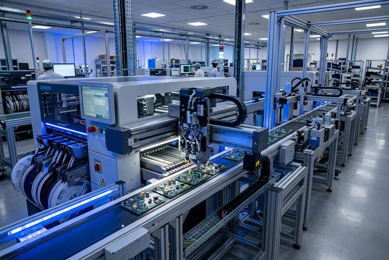
Keli Automation's post-reflow SMT automated production line integrates all seven stations into a cohesive system that handles PCBs from initial loading through final robotic unloading, with each transition precisely synchronized for maximum throughput.
Station Overview and Flow Sequence
| Station | Function | Key Components | Cycle Time |
|---|---|---|---|
| 1. Manual Loading | Board introduction to line | Magazine rack, conveyor interface | Operator-dependent |
| 2. ICT Testing | In-circuit electrical verification | Bed-of-nails fixture, test electronics | 15-45 seconds |
| 3. FCT Testing | Functional circuit verification | Test fixtures, power supply, data logging | 20-60 seconds |
| 4. Dispensing | Adhesive/coating application | Precision dispenser, vision alignment | 10-30 seconds |
| 5. Flip & Mark | Board翻转 and identification | Flip mechanism, laser/inkjet marker | 5-10 seconds |
| 6. Depaneling | Panel separation | Router/V-cut/punch system | 10-20 seconds |
| 7. Robotic Unloading | Finished board handling | Robot arm, vision system, magazine | 5-8 seconds |
Station 1: Manual Board Loading
1 Board Introduction to the Production Line
The first station serves as the human-machine interface point of the automated line. Operators load PCB panels from incoming magazine racks onto the line's conveyor system. While this station is manual, it incorporates several important features that set the foundation for downstream automation.
The loading station includes barcode/QR code scanners that read each board's unique identifier, automatically logging it into the Manufacturing Execution System (MES). This creates the digital thread that follows the board through every subsequent station, enabling complete traceability from raw PCB to finished product.
Key Technical Features
- Magazine rack compatibility with standard JEDEC dimensions
- Automatic board width adjustment via SMC pneumatic cylinders
- Integration with MES for real-time production tracking
- Barcode/QR code scanning for board identification
- Conveyor speed synchronization with downstream stations
Station 2: ICT In-Circuit Testing
2 Electrical Integrity Verification
In-Circuit Testing represents the first quality gate in the post-reflow process. The ICT system uses a bed-of-nails fixture — a custom panel of spring-loaded pins that make contact with specific test points on each PCB — to verify the electrical integrity of every component connection.
The ICT station can identify opens (broken connections), shorts (solder bridges), missing components, incorrect component values, and misoriented polarized components. For a typical board with hundreds of components, the ICT system can verify all connections in 15-45 seconds, a throughput that would be impossible with manual testing methods.
What ICT Detects
- Open circuits — broken solder joints or missing connections
- Short circuits — solder bridges between adjacent pads
- Wrong values — incorrect resistors, capacitors, or inductors
- Missing components — unpopulated pads where components should be
- Wrong orientation — polarized components installed backwards
- Component defects — damaged or out-of-specification components
Station 3: FCT Functional Testing
3 Real-World Performance Verification
While ICT verifies individual component connections, Functional Circuit Testing goes further by powering the board and verifying that it actually performs its intended function. FCT simulates real-world operating conditions, applying appropriate input signals and measuring output responses to confirm proper circuit operation.
The FCT station is typically customized for each product type, with dedicated test fixtures that provide the necessary electrical interfaces. Modern FCT systems can test multiple functions simultaneously, dramatically reducing cycle time while maintaining thorough coverage. All test results are logged to the MES database for complete traceability and statistical process control.
FCT Capabilities
- Power supply voltage and current verification
- Signal path integrity testing
- Communication protocol validation (UART, SPI, I2C, CAN)
- Analog circuit performance measurement
- Digital logic functional verification
- Thermal performance monitoring
Station 4: Automated Dispensing
4 Precision Material Application
The dispensing station applies various materials to the PCB as required by the product specification. Common applications include thermal interface materials (TIM) for heat dissipation, conformal coatings for environmental protection, structural adhesives for mechanical reinforcement, and underfill materials for BGA component reinforcement.
Precision dispensing systems controlled by vision alignment ensure that material is placed exactly where needed, with consistent volume and shape. This level of accuracy is essential for modern electronics where component density leaves minimal margin for error.
Dispensing Applications
- Thermal interface materials for heatsink attachment
- Conformal coating for moisture and contamination protection
- Underfill for BGA and CSP component reinforcement
- Structural adhesive for connector and component securing
- Potting compounds for complete module encapsulation
Station 5: Board Flip and Marking
5 Orientation Change and Identification
The flip station serves two purposes: mechanically turning boards for access to the opposite side, and applying identification marks for traceability. For products requiring dual-sided processing, this station automatically rotates the board 180 degrees using precision mechanisms that prevent component damage.
Simultaneously, the marking system applies permanent identification to each board — typically using laser marking or inkjet printing. This identification links the physical board to its digital record in the MES, enabling full traceability throughout the product lifecycle.
Station 6: Automated Depaneling
6 Panel Separation
The depaneling station separates individual PCBs from the manufacturing panel array. Depending on the panelization method used, this station may employ routing (for routed panels), V-score breaking (for scored panels), or punching (for tabbed panels). The choice of method affects edge quality, stress on components, and overall throughput.
Modern automated depaneling systems incorporate dust collection to maintain cleanroom compatibility and force monitoring to ensure consistent separation quality. The system automatically adjusts parameters based on the panel type loaded, with recipes stored in the PLC for rapid changeover between products.
Depaneling Methods
- Router-based: Best for complex contours, lowest mechanical stress
- V-score breaking: Fastest method for straight-line separations
- Punch/press: Highest throughput for high-volume production
- Laser: Zero mechanical stress, ideal for ultra-sensitive components
Station 7: Robotic Unloading
7 Automated Final Handling
The final station uses a robotic arm to pick finished boards from the conveyor and place them into outgoing magazine racks or directly into packaging. Vision systems verify proper placement and may perform final visual inspection criteria such as checking for labeling accuracy or cosmetic defects.
The robotic unloading system is designed for gentle handling to prevent damage to completed assemblies. Servo-controlled motion profiles ensure smooth acceleration and deceleration, while force-limited grippers prevent board damage from excessive clamping pressure. The system automatically tracks which boards go into which magazine slots, maintaining the complete chain of custody.
Integration and Data Flow
What makes the 7-station line truly powerful is not just the individual stations, but how they work together as an integrated system. The Mitsubishi PLC serves as the central controller, coordinating board movement between stations and managing the overall production flow. The Advantech industrial PC collects data from every station, creating a comprehensive production record for each board.
Every board that passes through the line generates a complete data package: incoming identification, ICT test results with individual measurements, FCT test data with functional parameters, dispensing records with volume and placement verification, depaneling parameters, and final inspection results. This data is available in real-time for production monitoring and can be exported for quality analysis and regulatory compliance documentation.
Learn more about our complete SMT production line solutions or explore how our battery equipment integrates similar automation principles for next-generation energy storage manufacturing.
Need a 7-Station SMT Line for Your Factory?
Keli Automation designs and builds complete post-reflow SMT production lines configured to your specific product requirements. Contact our engineering team for a customized solution.
Request Technical Consultation📞 (+86) 400-076-9629 | ✉️ info@e-kli.com